
Installing an RGB modification board in a PAL N64. Dismantling the console and installing the PCB. Testing and comparison with composite.
N64 and RGB video overview
Nintendo seemed to have a funny relationship with the RGB video standard on their consoles. The Famicom and NES used RF and Composite respectively, but most TV sets in the 80’s only used these formats. Jump forward to the early 90’s and the SNES was kitted out with the ability to output RGB with a suitable cable on all consoles.

|
With the release of the N64, Nintendo reused the same AV connector from the SNES, but only early NTSC US N64 consoles have a DAC chip that make the RGB signals. Later revisions and all PAL N64’s video decoder had no ability to output RGB. Only fuzzy composite. The reason given was that RGB wasn’t often used by users on survays.
RGB for PAL N64 Solution
If you have an NTSC N64 then making an RGB amplifier to get great RGB video is quite straight forward. I covered it here. Until recently If you had a PAL N64 then you have no options for RGB. Now there is a solution!

|

|
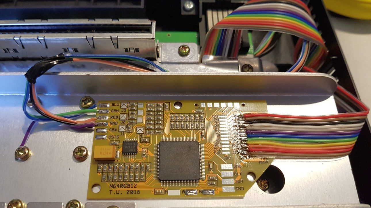
A talented developer called Tim Worthington (etim) put together a PCB based around the widely used Altera MAX II CPLD. The CPLD is programmed to be a complete replacement for the original N64 DAC. This will give the PAL N64 the ability to output RGB that we desire.
Installation
The installation of the PCB is both simple in its process and steps, but involves a bit of fine point soldering.
Firstly I dismantled the console and exposed the motherboard. The N64 is very well constructed and you’ll have to remove a load of screws to remove the heat-sink. It always strikes me how much smaller than the inside of the case.

|

|
Now we identify the DAC chip and solder a ribbon cable to the input side. The DENC-NUS DAC (for PAL consoles) is located next to the main GPU.

|

|

|
Once the cable is attached it can be folded as shown. Now the other end of the ribbon can be soldered to the PCB, making sure to get pin 1 the correct way round.

|

|
Next the output from the RGB board is linked to the unused pins on the underside of the AV socket. The typical installation only needs Red, Green, Blue and Ground soldering to the port. The sync signal is already present, Unless you want to switch to c-cync.

|

|

|
At this stage you can test the setup if you have a correct RGB cable. Its not recommended to run for more than a few minutes without the heat-sink, but that’s fine for a quick test to check things are working correctly. The PCB can be mounted on the heat spreader when reassembling. Don’t worry, it doesn’t get too hot there.
Image Comparison
I was very impressed with the RGB video output from this mod board. Its just as good as my NTSC N64 with an RGB amplifier. Lets see how it compares to the same console outputting standard composite video. Photos taken from a standard LCD TV. The image on a real CRT is fantastic but very hard to photograph due to refresh rates.
Mario Kart 64. Composite on the Left, RGB on the Right.

|

|

|

|
Star Wars Rough Squadron. Composite on the Left, RGB on the Right.

|

|

|

|
So as expected, The RGB image is much sharper, cleaner and with bolder colours. The results CRT displays will look even better than the images above, and will make a huge improvement for HDMI upscale kit.
8bitplus 2017.
only certain NTSC models can be easily RGB modded..
show us pls where the cables are connected from RGB chip to the underside of AV socket.
recommended to use sync on luma RGB SCART
How can I get CSYNC along with this mod ? I prefer CSYNC because Sync on Composite/Luma don’t give as a great picture quality as CSYNC.
Hey. I have just received the board through the post and am planning on trying it myself (I may well chicken out and need your services to fit it….will let you know!) Just one question – I have a PAL SNES RGB cable from Retrogamingcables, and it’s the Csync version. I’m hoping to use this with my N64. Do I need to wire CS# or CS75 to pin 3, or am I not understanding things correctly? I’ll be running the system through an OSSC…
Cheers
Where can I buy this kit? I’ve only soldered once before when fitting a backlight to a Gameboy ….this seems quite involved but I still want to give it a go.
Hi. You can get it here: https://etim.net.au/n64rgb/
I’m more than happy to provide and install this mod if needed. Just send me an email.
Hey. I have just received the board through the post and am planning on trying it myself (I may well chicken out and need your services to fit it….will let you know!) Just one question – I have a PAL SNES RGB cable from Retrogamingcables, and it’s the Csync version. I’m hoping to use this with my N64. Do I need to wire CS# or CS75 to pin 3, or am I not understanding things correctly? I’ll be running the system through an OSSC…
Bloody brilliant! The difference in the picture is night and day! When the console is capable of such a great imagine why did Nintendo give us such crap to start with, it baffles me!?