
Adapting Neo-Geo MV1A arcade board to a console. Consolised MVS board. Audio,video and controller port installation port installation.
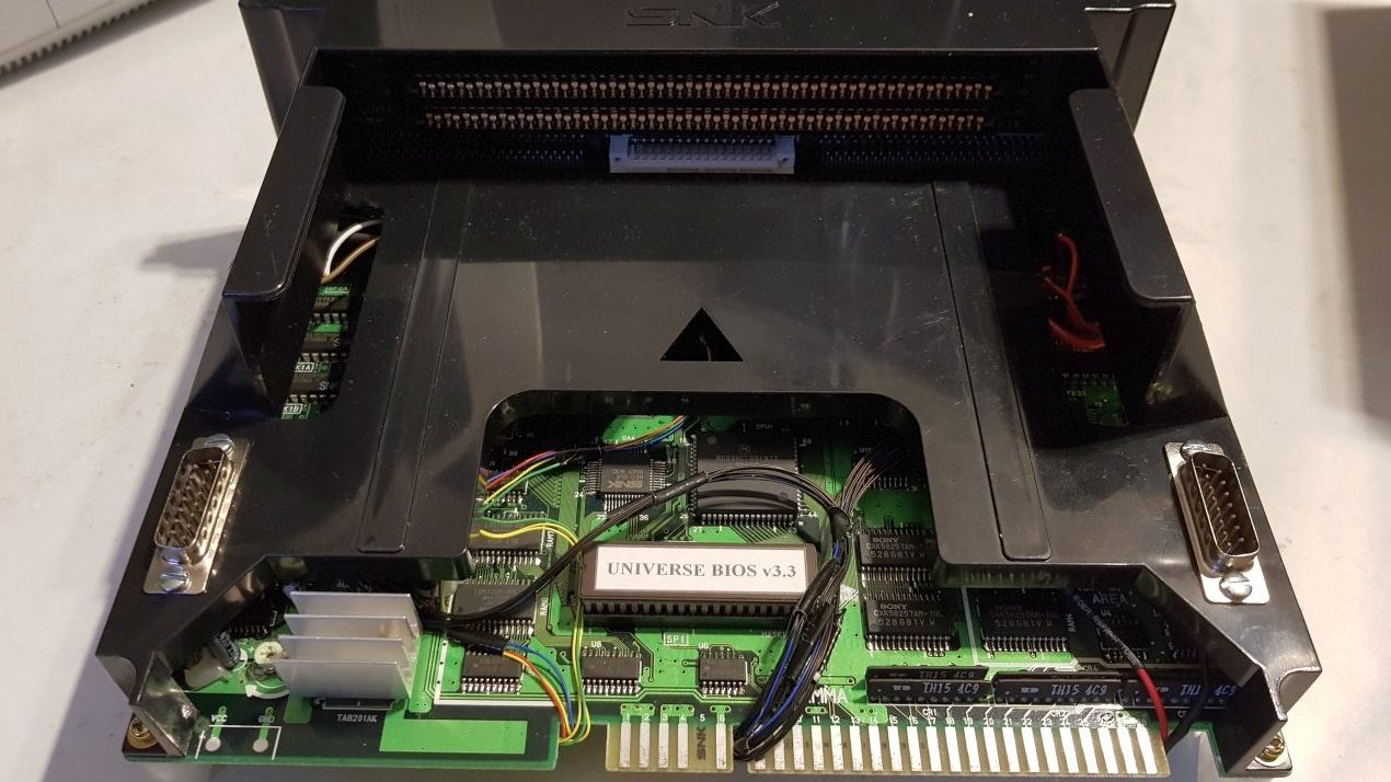
MVS Console
Anyone can enjoy playing Neo-Geo MVS games at home with a supergun (like this), or a good arcade cabinet. Sometimes though setting up the supergun is inconvenient, and the cabinet may not be an option to some people. Emulation is always a fallback, but nothing beats the real hardware. Another solution is to convert the MVS boards into a console. All that’s needed is some planning and a few parts.
I was asked to do a consolised MVS conversion for a customer. we discussed building a basic RGB Supergun from scratch as he wasn’t satisfied with the video quality for his existing unit but settled on the conversion.
How does it work
Simply all you need to do is recreate the basic supergun components within the MVS case. Power, Video, Audio and Controllers.
Power
The one slot Neo Geo arcade Jamma boards make use of DC 12v and 5v power. The 12v powers just the audio amplifier, while 5v drives everything else. The Audio amplifier can be switched to work on 5v with a few modification found here. Basically all that needed is to isolate the 12v line and pass the 5v in its place.

|
The power supply I selected is a 2.5A 5v unit, this is plenty for the one slot Neo’s. I’d also need to install a switch and fuse for safety and a LED to indicate its running.
Video
The video is tapped off the Jamma edge connector and runs to a 8pin DIN socket. I wired it to match the wiring for the Neo Geo AES and CD consoles so the same RGB Scart cables can be used.

|

|

|
Now the power and video lines were attached I could start testing. Below you can see the video test screen and game play from King Of fighters 2003.

|

|
Controls
Linking up the controller ports is simple but very fiddly. I have used DB15 connectors so that original Neo Geo CD or AES controllers and joysticks can be used. All the wires are linked up below the jamma edge along the resistor banks.

|

|

|
You need to just connect a wire for each of the player inputs from the board to controller ports. Its helpful to have a copy of the port pin-outs handy. I mounted the controller ports on top of the case. The small amount of plastic on the sides would also work, but you have more chance of breaking the case while cutting/drilling.
Audio
Jamma boards output ready amplified audio ready to connect speakers. To use the audio on a TV we must tap the signal level audio before its gets to the OPAmp chip. I also had to make a small amplifier to raise the line audio to the level needed for a TV or external amplified speakers.

|

|

|
The full diagram and singal tapping info can also be found on JammaX. This circuit can be used on all the 1 slot MVS units, just with different tapping points. The audio can be outputted to the AV port, jack connector, or even both.
Finishing
So the final product turned out very well and works great.

|

|

|

|

|
There we have a quick and convenient solution to playing MVS games on a RGB TV.
8bitplus – 2017
Hello! good afternoon! Could you pass me the value of the resistors? I can’t see them. are the following
R64 R63 R56 R57 R50 R49 PC29 R58 R48 R51 R47 R46 R44 R45 R62 R52 R61 R60 R53 R55 R54 R59
some are very little noticed
I keep seeing references to building this additional circuit when tapping for stereo. Is the signal that is directly tapped from before the amp not sufficient for line-level output (if using TV audio amp or a separate stereo amp)? What would happen if this was omitted? Low audio? I’m seeing people tapping the L/R legs before the amp on MV1C boards and sending directly to RCA jacks.
For the sake of people who would have the same question :
I tried connecting to the 3 resistors as seen on the Jamma-X tutorial, without the RC circuit. Works like a charm, sound is all good on my tv. I’m out of the required components to try the setup in the tutorial (as I’m writing this, we are in full COVID19 lockup, so every seller is closed), so I cannot try the circuit to tell you the difference.
Although I barely hear system sounds (that “bleep” when you insert credits), so maybe it’s meant to amplify this frequency? But I doubt it.
Hi,
Great guide, just a couple of questions, What size are the resistors on the RGB out (into the socket)and were do you connect the sync.
what are the values of the capacitors and the resistors
In what? The whole board? Ask at the Neo-Geo forums.