
This project covers the removal of the original Sega Nomad LCD screen, and upgrading it with a newer and better LCD.
Sega Nomad

|

|

|
The Sega Nomad was a portable Sega Genesis launched only in North America in the mid 90s. Its basically a Sega MegaJet with a screen. It also featured a controller port for a second player, and an AV out port for TV play.
A good idea in theory, but the Nomad was let down by a number of factors. Including rushed design and a poor quality (even for 1995) screen.
There’s an area of debate around the screen quality on the Sega Nomad being worse or same as the Game Gear. I personally think the screen is very much the same, but the Megadrive/Genesis games run at a higher resolution and at higher speed than GG games. This makes the screen blur and ghosting more noticeable. Fine detail is almost completely lost in moving sprites.

|

|
Apart from its shortfalls, its a nice system and with this modification can be made much more playable.
I happen to own 2 Sega Nomads. the first one is in very good condition and boxed. The other is un-boxed and a bit more used in appearance. This is the one I will modify.
Theory
The inclusion of the AV port is the key to this mod. Without it replacing the screen would have been much harder, or not possible at all. Along with the RGB output and audio, the Sega Nomad outputs composite video. There are many 3.5″ TFT screens on the market that can use this signal.
All that’s required is to wire a new screen to the video signal, and power.
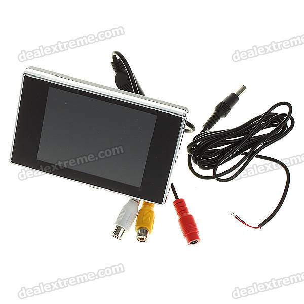
New Screen
The replacement screen is a generic model often sold for car DVD players and reversing cameras. They are produced in many forms and can be found very cheaply on Amazon, Ebay or dx.com. just Google “3.5” TFT”
The first this that should be mentioned is that NOT all of them will work. Some of the screens cannot correctly sync to the genesis NTSC signal and resolution, so you always need to test them out first.The first screen I got from eBay (looks like this type) didn’t work. All I could get was an unstable and badly colored mess. even though it worked on other video scores like Neo-Geo and Raspberry Pi. This must be down to the signal processing logic on the screen, nothing can be done about it….. Try again.
The second unit (this one) also didn’t work, exactly the same problem.
The third one (this one) DID WORK! At last we can continue…

|

|

|
You can already see how much better the screen will be.
Installation
After testing the screen externally it was time to strip the unit down and remove the old Nomad screen. the nomad is very easy to open so I don’t need to go over it in detail. just remove the screws and disconnect the cartridge ribbon connector carefully.
Next remove the smaller screws from the motherboard and the speaker wire, then lift it up.

|
Now for the point of no return, remove the original screen (4 smaller screws) and cut off the connector ribbon and disconnect the back-light power. I found that the ribbon almost peeled off. I then covered the connection with electrical tape to prevent anything touching.

|

|
Now to solder the connections for the new screen. Connection points for power and video shown below.
Notice below that I have soldered a jumper wire (white wire) to the driver board.
The reason for this is to bypass the DC step-down circuit on the board. In normal use the board would take 12v from the car power system and convert it to 5v for the LCD display. By bypassing this, and providing a lower voltage we extend the battery life. Some guides don’t do this, and the it can cause flickering display problems.

|

|

|
Fit new screen
Now to test the setup again after making the connections.
I found it’s best to attach the new LCD to the front case shell rather than to the motherboard as the old one was. Get it aligned up and glue in place. then glue the LCD driver board to the screen with a layer of plastic as an insulator from the PCB.

|

|
Once its all back together and tested, its time to enjoy some smooth clear Genesis gaming.

|

|
The improvement is huge. Its so much more playable. Moving graphics are so much easier to follow. I know some people have some reserves when modding an old console like this, but its worth doing if your Nomad inst in perfect condition in the first place.
The only drawback is the gamble to find a compatible screen, but when you do it’s not too hard to install. Also if this screen stops working at a later point its easy to replace again.
Thanks for reading. Please feel free to send any question or comments below.
8bitplus – 2015
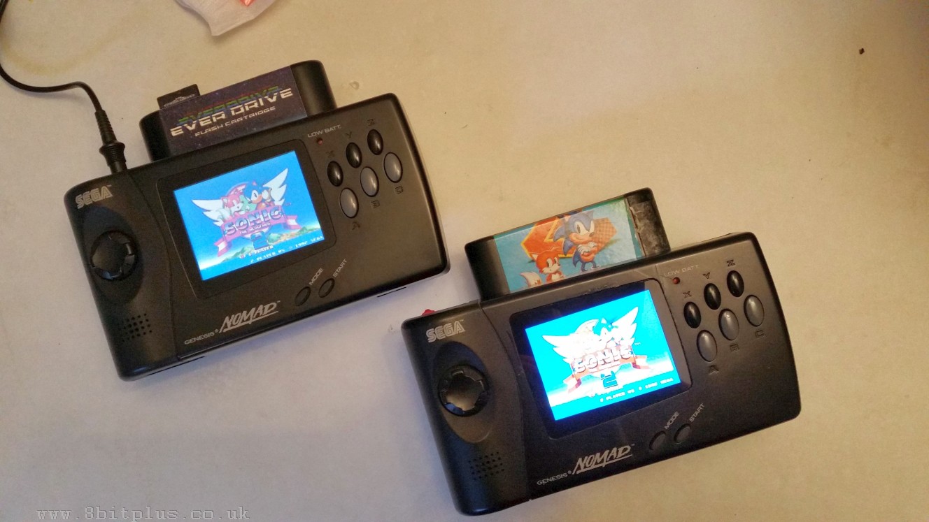
Comparison
Here are a few comparison photos of my modified Sega Nomad and an original unit.

|

|

|
Notes
Make sure you do some research on the display you plan to use. Be prepared, you might need to get several displays before finding one that works.
Check out the rechargable battery I built after replacing this screen.
Battery Mod.
Credits
Thanks to:
www.racketboy.com – for the initial idea.
https://nobitleftbehind.wordpress.com – for more info and screen flicker solution
Hello
To bypass the 12v into 5v like you have done with the wire, does this ground pin 3 of the chip or does it push 5v into the chip, the reason I ask is that I have received a newer revision in where the chip and resistor is located somewhere else so if it’s gnd I can use any gnd point.
Thank you
Hello,
The DX link to the screen that worked for you now has a different model board. The current pictures on the item page are that of the board I received. There are four solder terminal/holes marked 3V3, GND, TX and RX. Can these be utilized instead of cable connection? Will I need to convert the 5V out of the Nomad to 3.3V to use this? Thanks for your input.
Hi. I haven’t ordered any of there screen for some time. If they have changed the model then you can try with caution. Might work, Sorry I just cannot answer that any better for now.
I used your information on this page for my YT video here: https://youtu.be/AZ5aytv9oIs
Though I find your “jumper” for the voltage regulator unecessary. Otherwise, great work.
Just A quick update, My modded Nomad (thanks 8bitplus) continues to work a treat with the new screen, modded screen dimmer and re-chargeable battery mod in place.
Now if only the Atari Lynx II was so simple and reasonable price wise!!
Sorry for the late question. can the eight pin 12V to 5v regulator chip just be removed altogether instead of soldering the bypass cable?
It can indeed, I’ve seen that done somewhere. You could even solder the 5v line to the output of the regulator. Lots of different ways to do this.
Wow, super quick response. So if the chip is removed, that is all that’s required? You’d think with a chip missing something would break/no longer work wouldn’t you 🙂
p.s. To date I’ve done all the above minus the bypass (as my soldering skills are not good enough, neither is my eye sight!) and yes, the screen is more off than on. With the power adaptor connected no problem whatsoever.
I haven’t tried removing the regulator myself. It might have been a different screen type to mine. Id just bypass it personally. I think you’ll get more screen time with the bypass. What battery are you using? my rechargeable make a huge difference
I’m using the standard Nomad attachable battery pack with Duracell Alkaline, I’ve not seen a rechargeable battery pack (here in the United Kingdom) for the Nomad (it was never sold over here!).
I could upgrade that with Li-ion cells very easily.
http://8bitplus.co.uk/projects/nomad-rechargeable-battery/
I’m in the UK. Send me an email if you re interested. 8bitplus@gmail.com
You realize that the jumper wire you soldered in does not do anything right? Basically, you just wired the output voltage from the step-down converter to where it was already going on the board- the inductor.
Hi, thanks for your tuto.
I would like to mod a game gear. Do you think this screen is available for game gear ?
If it’s ok, can you help me to do it ? I have tested an other mod (McWill), he asked to take off some resistanc, do you think it’s the same think with this screen ?
Thank you
Hi. This is not the same screen used by the McWill GameGear mod. If you get the McWill kit I’m happy to do the mod for you. Send me an email from the contact page. Regards 8bitplus
I have done the mod, but in fact, his mod is a little expensive and I am looking for another mod cheaper…
In a game gear, pin 42 of the game slot is for resolution… Do you think if I solder wire composite in the pin 42 I will have a good resolution ?
No. That pin is related to the GG TV tuner accessory is a mode switch. The GG has no Composite signal on board at all. You would either need to install a RGB screen, or a RGB to Composite converter.
i’ve actually done well with the first lcd you tried. I remove the 12v-5v down converter completely with my hot heat gun’s smallest nozzle and bridge pins 1 and 2. I think the color and issues were from undervolting. I actually bought those screens a couple years back too.
I have the recommended screen going in one this weekend, i will remove it’s power converter as well and bridge the chips. less chance of fuss later. I don’t recommend anyone who doesn’t have a heat gun to try and remove though. these tiny boards are to easy to ruin.
I wish I could find an screen that takes analog RGB in cheap, lol. That mod may happen though.
Hey, looking to buy the screen to do this mod but don’t want to spend as much shipping the screen as the cost of the lcd. Are there any online stores in NA that sell these parts?
Hi Tim.
Very sorry but apart from eBay I don’t know where you’ll find them in America. Perhaps something like Aliexpress…. The best answer is any of the 3.5″ screens “might” work. You might have to just try and see.
Mr Major, free shipping sir. http://www.dx.com/p/2-ch-video-input-3-5-tft-lcd-display-monitor-module-w-cable-black-silvery-grey-ntsc-pal-201631#.V-7uBvArIUG
The screen you posted is sold out.
Can you please help me find another one?
Hi Karl. I just got a couple of these from ebay: 281945486708 and they worked fine on a recent Nomad mod.
The image difference is immense when comparing the original screen to the LCD replacement, a highly recommended mod for any nomad owner and relatively cheap, I would advise on spending a little more on your LCD to ensure that any sync / blur, frame rate issues are reduced.
I agree on the before and after difference, but spending more on a screen won’t make any difference in quality. The screens are composite and intended for car reverse cams and small projects
Hi, i used the same model of screen and this was my issue… https://www.youtube.com/watch?v=REwkctfpd50
what i’m doing wrong?
Same model as mine? Looks like it cannot sync to the Nomad correctly. As with all cheap electronics something could be wrong, or slightly different in each batch. Keep trying, I went through 4 before I found one that worked….
For those of you that DO NOT have the same LCD controller board. What you can do is cut off pin 4 of the DC to DC step down converter chip and bridge pin 1 and 2. This will completely disable the chip and feed straight 5V to the LCD panel.
This worked on the newer style board! Thanks!
Hi there, could you install.back the originan screen later if you wanted to?
No. Removing the original screen connection make it impossible to reinstall. But luckily I have 2 Sega Nomad’s 🙂
I have seen that screen in game doenst work full. For ex, sonic game had blue trce in each side of screen. Why that appear? Have any way to full screen
The genesis/MD does not output exactly 480 lines. the rest of the area is called “overscan”.
Find yourself a screen that has digital zoom or overscan cropping. Good luck.
I bought the same LCD as the one that worked for you, but am only getting a blank white screen when turned on. Wondering If they changed something on the board and it doesn’t like the signal or if I got a bad one.
It’s always possible it changed at some point.
Have you checked the nomad video out signal with anything else? when I was testing I used a AV out cable to a CRT TV. I was going mad to find a LCD that would sync.
Another idea. did you test the LCD screen on anything else? plug it into anything else with a composite output. I tried all the 3.5″ screens out on a PS1 and Neo-Geo.
I boght five screens and two come bad. One with ribon cable broken and another blank.
At that price I would expect problems in some…….
I bought two of the screens that claimed worked and they both did but flashed. So did your 12V bridge and it killed both of them. Power was still going around the board but nothing would display on either screen anymore.
The screen I found that worked was this one:
http://www.dx.com/p/2-ch-video-input-3-5-tft-lcd-display-monitor-module-w-cable-black-silvery-grey-ntsc-pal-201631#.VW1uM89VhBd
not any of the others I tested.
What voltage was connected after you did the DC bypass? because if you still had it linked to the 12v that’s how you killed it.
Why you show 4 arrows, two from 5v and two from the ground? I need make a bridge betwen red arrows and other betwen black arrows?
Just to show they can both be used. your choice.
Just finished mine! Looks amazing :)! Great tutorial, thanks.
I just wanted to say thank you for the info you provided. I just finished this mod on my nomad and it turned out perfect!
I just bought the same lcd that worked for you. The first one that I got was the same one as the second one that didn’t work for you. I had a question regarding the wiring, I see that you removed the white wire. Is this not needed? Also what voltage battery are you using? I’m modifying my battery pack with a 7.4 volt battery, would that be alright? Thank you for any help you can provide.
I just bought the lcd that worked for you. The first one I got was the same as the second one that didn’t work for you. I had one question regarding the wiring, I see that you removed the white wire. Is this not needed? Also what voltage battery are you using? I’m modding my battery pack with a 7.4 volt battery pack, would that be alright? Thank you for any help you can provide.
Hi. The white wire is not needed so I removed. Its a 7.4v battery in my mod. That’s the correct voltage to use.
Please note. the connections that I used to power the screen are only 5v. To make the LCD work you’ll need to bypass the DC converter chip on the LCD driver board. You can see the little white wire I used to do this.
Just what I needed to know. Sorry I posted the same question twice, didn’t realize the first 1 went through. Thank you for your help.
Is this the screen you used?
http://www.ebay.com/itm/3-5-inch-TFT-LCD-Car-Rear-View-Digital-Monitor-DVD-VCR-2CHs-Video-Gadgets-gi-/251584933137?pt=LH_DefaultDomain_0&hash=item3a93a16d11
I bought two of these and neither worked…
http://www.amazon.com/3-5-Inch-TFT-Monitor-Automobile/dp/B0045IIZKU/ref=sr_1_1?ie=UTF8&qid=1427940041&sr=8-1&keywords=3.5+inch+tft
And one of these, it didn’t work either.
http://www.dxsoul.com/product/3-5-tft-lcd-monitor-visual-reversing-vehicles-reverse-camera-ntsc-pal-dc12v-901057274#.VRyig-H6dBw
I know I did everything right on my end, but I read some forums and a lot of people said that they have the same issue as me… so trying a new one. Please help! And great tutorial btw 🙂
Haha just noticed that you said the exact same thing. Getting the 3rd one you said that worked 🙂
Hi.
Looks like you went through the same process as me. Third time lucky.
That’s the one, hope that works for you. Don’t forget to bypass the DC converter and link to 5v.
Hope it works! Thanks 🙂
Hi, can this mod me done on a Game Gear too?
In a way yes. But the GG dons’t have any composite output from the video systems. There is a mod pcb that can provide composite, then a new screen can be added. The next problem is that the GG runs in a very low resolution, so the picture is a small square in the middle of the screen (unless you can find one with a zoom function). Not worth it I think.